Capturing Serial Printer Data From Industrial Machines
One of the oldest methods of connecting computers and other equipment, including printers is through the serial port (later known as COM ports under Windows). With an easily obtainable and low-cost USB to RS232 serial adaptor plugged into a Raspberry Pi you have an instantly available serial port (normally seen as /dev/ttyUSB0) – how difficult can this be?Well, recent experience trying to connect to various automated bagging/weighing machines at one client’s factory revealed some of the issues.
When tackling any sort of serial connection, the main issues are around identifying the type of connection (a DB25 connector can be many things!) as well as existing settings. If there is a printer which is still working, then the first port of call is to at least print off any settings (such as baud rate, stop bits etc), or finding a set of DIP switches which might be at the back of the printer (or hidden away inside) to at least give a starting point. Manuals for the printer and machinery also help, as can finding support from existing contacts within the automation industry who may have previous experience of the machinery.
In this instance, the age of the equipment did not help – manuals were only available for one bagging/weighing machine, and most of the original suppliers had gone out of business.
Thankfully, 2 of the 4 types of machine had partially working printers and one of the other machines had a manual. It is never a good sign when you contact someone who has taken over the original machine manufacturer and they tell you that you need to replace the whole machine – something outside of our client’s budget, but we were not perturbed and decided to get back to basics, working closely with an electrical engineer at the client, to investigate the various communiccations standards used for each machine.
So lessons learnt – first of all work out which serial communications standard is being used – there are several which we have come across, so getting the Retro-Printer to communicate with the original equipment may take some experimentation to assess the standard being used, if it is not documented.
a) RS232 – the main standard.
In the past whenever we connected serial ports, you just need to know the BAUD rate (speed at which the communications work), how many bits the data uses (typically 7 or 8), and maybe a stop bit (either 1 or 2 bits to indicate the end of transmission). Usually, inputs are connected to outputs – and outputs to inputs.
You then need to determine if the RS232 port needs to be configured as a DTE (Data Terminal) or DCE (Data Communication) device, as output pins on a DTE port need to be swapped over to the input pins on a DCE device and vice versa. That is why you sometimes need a NULL Modem cable which does this swapping over of pins.
Thankfully, most printers (and computers) are configured as DTE devices and existing cabling should already handle any swapped pins (assuming you have the original cable). Otherwise, for most printers, you will need a NULL modem cable.
The exact type of cable and wiring will depend on whether the serial port has 9 pins (DB9) or 25 pins (DB25) and even if there is handshaking included.
You may of course, need an adaptor to convert a 25 pin connector to a 9 pin connector, depending on your cable and the end of the USB RS232 adaptor you have plugged into the USB port on your Raspberry Pi.
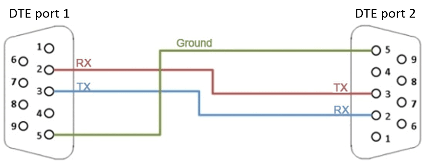
RS232 DB9 to DB9 Printer Cable no Handshaking
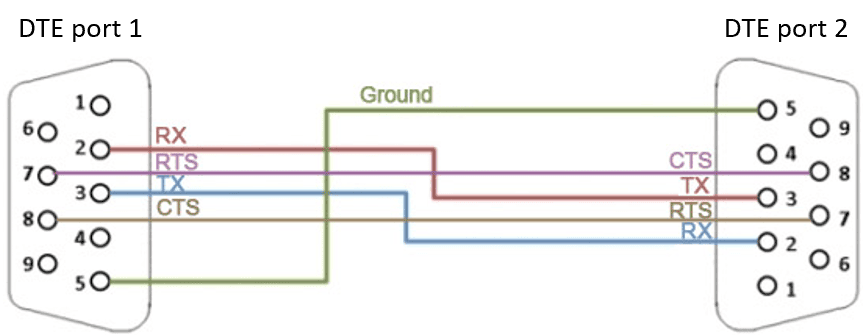
RS232 DB9 to DB9 Printer Cable with Handshaking
RS232 Stop Bits
A stop bit is used to indicate the end of a data frame or byte, ensuring that the receiver is ready to process the next frame – it marksthe completion of data transmission for a specific character, byte, or frame. The stop bit also helps the receiver synchronize with the incoming data stream, ensuring proper interpretation. Most equipment uses 1 stop bit, but some may use 2 or even 1.5 stop bits.
The Retro-Printer supports either S1 (1 stop bit), or S2 (2 stop bits)
RS232 Parity Bit
Parity is used as a simple error-checking method where an extra bit (the parity bit) is added to each byte of data – ensuring that either an even or odd number of 1s appears in the transmitted data. This allows the receiver to detect potential errors during transmission.
- None – No parity bit is sent
- Odd – The parity bit is set to ensure that there is an odd number of 1s in the data byte
- Even – The parity bit is set to ensure that there is an even number of 1s in the data byte
- Mark – The parity bit is always set to 1.
- Space – The parity bit is always set to 0.
These methods do not always detect bit errors (eg if 2 bits in a byte are incorrect) and cannot correct errors but you need to check whether your equipment uses any of these settings.
The Retro-Printer software now supports all of these potential parity options.
RS232 Handshaking
- RTS/CTS: Using the CTS and RTS lines to signal the equipment when the equipment is requesting to send a byte of data (RTS) and when the printer signals that the equipment is clear to send the byte (CTS). This requires 5 lines connecting the equipment as shown in the second image above.
- XON/XOFF: This represents the software on the printer telling the equipment that Transfer is On (XON) and Transfer is Off (XOFF) – the equipment then sends the byte when it gets the XON signal.
- DSR/DTR: Using Data Set Ready (DSR) and Data Terminal Ready (DTR) signals – this is less common, but uses pins 4 and 6 on the DB9 connector above
The Retro-Printer software now supports all of these potential handshaking options.
RS232 Oddities – Wiring
We came across one instance where an autoclave was attached to an Epson LX-300 printer. The pinouts were somewhat unusual with wiring to pins 3 (RxD), 7 (Ground) and Pin 11 (normally unused).
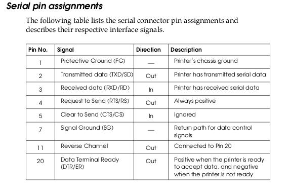
Epson LX-300 RS232 pinout
It transpired that this was an implementation of DSR/DTR handshaking using Pin 11 as the DTR output. We therefore had to create our own DB9 to DB25 adaptor to plug into a standard USB to RS232 cable – we did this by connecting the following pins:
DB25 DB9 RS232
3 RxD ———— 2 yellow TxD
7 GND ———— 5 white GND
11 ———— 4 red DTR
Shield ———— Shield black
RS232 Oddities – Voltages
One issue which has caused some problems is that some RS2322 ports are reliant on +/-12v signals. That is normally fine on a computer with built-in RS232 COM ports – however, those are now hard to find. The vast majority of USB to RS232 convertors do not get sufficient power from the USB port on the Raspberry Pi (or a PC) to be able to deal with the higher voltage. After ome searching, we have now found one supplier who continues to make USB to RS232 adaptors which can support the +/-12v.
b) RS485 standard.
Another machine we needed to capture data from was a PLC using the RS485 standard for communications. The first challenge here was finding the settings in the setup screens to enable this port as a printer COM port (rather than a data bus or programming port). Thankfully, there was a manual for the system.
RS-485 is a communication standard that enables multiple devices to share a single two-wire bus line for data transmission. Normally used for half-duplex communication (where devices transmit and receive data sequentially on the same wires) in this instance there were 5 wires available.
RS-485 uses a differential signalling method – so you have a Transmit+ , Transmit- and ground. In this instance there was also a Receive+ and Receive-. The data is then represented as the voltage difference between the two Trasmit (or Receive) wires which helps the system work where there may be electrical noise. This also allows RS-485 to support long communication distances, typically up to 4,000 feet (1,200 meters), with a maximum data rate of 100 kbps at that length.
RS-485 also allows several commanding modules, and several listeners on the same cabling – meaning that it can be used to connect a whole system of inter-connected modules on the same circuit.
We used a special terminal block plugged into a USB to RS232 adaptor, to convert these signals to RS232 so that the Retro-Printer module can easily get the data. However, despite the manual saying that T+ and T- should be connected to T/A+ and T/B- we found that did not work, and we needed to cross-over the cable to connect the transmit with the receive signals. We therefore wonder if the printer COM configuration actually used the RS422 standard as below (depsite the clearly labelling of the port on the control panel as RS485).
RS485 Oddities – Voltages
The first issue we came across was that when we captured data, it was completely corrupt. Thankfully, from the manual we knew what the output should be (plain text), but we ended up with jibberish. We checked the baud rate settings, handshaking, stop bits etc (in our case, 19200 baud, no parity, 8 bits and 2 stop bits and XON/XOFF), but to no avail.
We found that we needed the USB to RS232 adaptor which supported +/-12v to work with this system rather than the adaptor supplied with the terminal block.
This may of couse vary dependent on your setup, but once using the +/-12v capable USB to RS232 addaptor, we captured the data faultlessly.
c) RS422 standard.
As with RS-485, the RS-422 standard uses a differential signalling method – so you have a Tx+ , Tx-, Rx+ and Rx-. However, it only supports one commanding module and multiple listeners (unlike RS-485).
The data is then represented as the voltage difference between the Trasmit and Receive wires which again helps the system work where there may be electrical noise as RS232 is reliant on the difference between a single wire and signal ground. This also allows RS-422 to support long communication distances, typically up to 4,000 feet (1,200 meters), with a maximum data rate of 100 kbps at that length.
Terminating resistors (usually 120 ohms) may also be used at the end of the cable to prevent signal reflections, especially at higher data rates and longer distances.
Thankfully, the special terminal block plugged into a USB to RS232 adaptor we used above would also support RS-422.
d) Current Loop standard.
This has perhaps provided us with the main challenge to implementing serial capture across the various printer communications standards. We came across an Epson LX-400 dot matrix printer fitted with an Epson 8143 Serial Card. There are minimal details on the serial card, beyond the DIP switch settings – and we could tell that the DIP switches were set for 1200 Baud, with +/-12v support and Current Loop rather than RS232.
The Current Loop is a standard developed originally for telegraph and teletype communication and was needed to allow serial connections over very long distances. Current Loops normally have an active node (such as a PLC) which supplies current at 0-20mA (some early versions can go even higher). Knowing the length of the cable run can be used to calculate the voltage required at the active node in order to ensure the signal reaches other equipment on the loop.
Normally 4 cables are used to supply Transmit Positive (T+), Transmit Negative (T-), Receive Positive (R+) and Receive Negative (R-). The passive equipment in the Current Loop (for example a printer) then merely needs to check if there is ANY current passing through a cable – it doesn’t care about the voltage levvels (required by RS232). The downside is that there is no form of handshaking – so the only fault which can be detected is a break in one of the wires.
There are a few current loop to RS232 adaptors available online, but unfortunately, in this instance, they proved unsuccessful in allowing the industrial controller to connect to the Raspberry Pi.
Current Loop Oddities – Wiring
The main issue came with finding any details about the DB25 connector on the Epson 8143 Serial Card. There is simply no information online and Epson UK pointed us to Epson New Zealand who were in turn unable to provide any information other than suggesting we contact the original printer supplier for support! We did however, find a couple of Epson intelligent serial interface manuals, which gave a clue as to what the pins were for (assumign the 8143 serial interface used the same arrangement).
The Richard Simon Computak II Controller (PLC) end of the cable had a DB9 connector, with no labelling and just three wires – Red, Black and a bare wire (in a yellow sleeve). Taking the DB25 connector apart at the printer end did not provide too much information – so we ended up with a cable looking like:
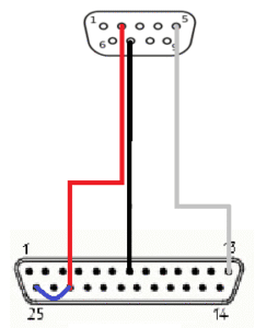 DB9 DB25
Pin 5 -> Pin 1 (GND) – bare wire with yellow sleeve
Pin 7 -> Pin 7 (Signal Ground) – black wire
Pin 2 -> Pin 23 (Input Data) – red wire
Note: Pin 23 (Input Data) was wired to Pin 25 (Input Data Return) with a 470 Ohm resistor (shown in blue)
The problem was then how to match this wiring with the RS232 to Current Loop convertor, where the contacts are marked:
T+ T- R+ R- RES1 RES2 RES +12V +12V RS-232 GND
Looking at the current loop options, the printer end had to be a passive current loop connection (as it did not supply +12V to the circuit). We therefore connected R+ to the Red Wire, R- to the Black wire and GND to the bare wire with yellow sleeve.

RS232 Epson 8143 Serial Interface (Boxed)
We still did not get any data, and were stumped – the manufacturer of the Current Loop to RS232 Adaptor suggested that this might actually be the analogue current loop standard. Without support from neither Epson, the Current Loop to RS232 adaptors, nor the original PLC manufacturer, we had hit a brick wall as to how to address this issue as there was no detail available.
Thankfully, after much searching, we found a (poor quality) copy of the schematic for the now rare Epson 8143 Serial Card from which we were able to fetermine the circuit details as used by the serial interface. We then decided to build a solution built around that original Epson Serial Card to convert the incoming Current Loop signal into RS232 standard. We found that we needed a system supplying 12v, 5v and a signal inverter (as the signal from the Epson 8143 communications card is TTL standard), we sucessfully manged to capture the data which was originally being printed by an old Epson LX-400 Dot Matrix Printer.
Having proven the system, we then used a 3D printed box to contain the Epson 8143 Serial Communications interface, plus all of the wiring required to ensure that it could be left safely on site. This modification enabled us to capture data from a Richard Simon Computapak II controller over the current loop circuit – something which we were told could not be done!
If there was sufficient call, we could replicate the current loop section of the serial interface, but that is probably not a worthwhile exercise as most people will be replacing an existing Epson serial printer and therefore should have the interface to hand.